6.1. Link layer
The link layer protocols allows us to cerate the
logical transmission channels on physical links. The role of the link protocols
is to ensure the reliability of communication on the links whose binary rate is
limited, the propagation time is important, and the transmission errors may
occur. These factors, to which the processing time is added, are taken into
account in the development of the protocols.
Concept of frame
The physical layer ensures
the transport of flows of bits These flows can comprise errors. The link layer
must detect these errors and correct them if necessary. For this purpose, the
link layer cuts out the bit flow in frames and calculates a checksum for each
frame.
Marking frames can be carried out according to three
techniques which implying:
•
the use of the special characters to mark the beginning and the end of
frame,
•
the use of the binary flags to mark the beginning and the end of frame,
•
the modification of physical coding at the beginning and at the end of
the frame
•
frame alignment through the recalculation of the error
detection/correction codes
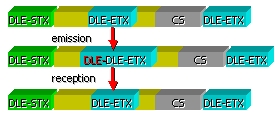
Special characters
The first technique exploits
the control characters to delimit a frame. The sequences of characters DLE STX
(Dated Link Escape, Start off TeXt) and DLE ETX (Data Link Escape, End off TeXt) are placed respectively at the beginning and at the
end of the frame.
When DLE STX and DLE STX sequences appear in the data to be transmitted,
the transmitter adds another character DLE
in front of each DLE character. The
link layer of the receiver removes DLE
characters added by the transmitter.
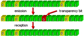
Binary” frame
A “binary” frame may contain an arbitrary number of bits. Each frame
begins with a particular sequence of bits 01111110 called flag
(hexadecimal 7th). When the link
layer detects five consecutive “1” in the data to be transmitted, it adds a bit
“0” before sending the completed bit flow on the line. When the receiver
receives five consecutive bits “1” followed by a “0”, it removes the “0”
automatically.
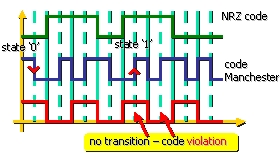
Violation of the physical code
When the physical code
contains redundancies, it is possible to introduce abnormal states to mark the
beginning or the end of a frame. For example the Manchester code
represents the bit “0” by a positive impulse (a half-bit) followed by a
negative impulse. The combinations positive-positive (HH) and negative-negative
(LL) are not used for the representation of data, they can be exploited to mark
the beginning/end of the frame.
6.2. Detection and correction of the errors
The errors of transmission
are due to various physical phenomena. The thermal noise is always present. It
is caused by the agitation of the electrons in the metal conductors.
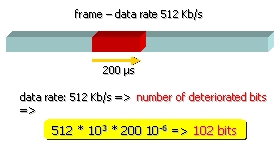
The
impulsive noise is another considerable phenomenon. It causes parasitic
impulses with periods of hundreds of microseconds. Such an inference may cause
the loss of several tens or several hundreds of bits..
Another
physical source of errors is due to the difference of the propagation velocity
of signals at different frequencies. Other errors, such as the loss of a frame,
can be implied by the structural limits of the network architectures. In
general all these intrusions tend to create packages of errors rather than
simple errors.
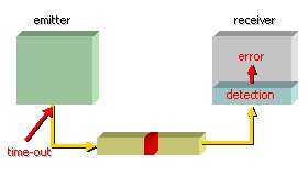
6.3. Two strategies for the error control
The designers of networks developed two strategies in
the field of the error control, of
error correction and error detection with retransmission.
•
error correction technique consists in
including in the frames sufficient data redundancy, so that the receiver can
restore the original data starting from the received data,
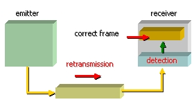
•
detection/retransmission consists in adding
just enough redundancy in the data to be transmitted, so that the receiver can
detect the presence of error(s) without being able to correct them.

6.4. Error correction
codes
In order to be able to
correct the errors, it is necessary to know the exact definition of an error.
Let us suppose that a frame is made of m
bits of data and r control bits. If
one notes n the length of the frame
(n=m+r), the whole of n bits will be called a codeword.
Being given two code-words,
it is possible to determine how much (bits) they differ.
Example:
1 0 0 0 1 1 0
1
1 0 1 0 1 0 1
0
For this example the number of differences called distance of Hamming is equal 4. In a
codeword it is possible to use 2m
combinations of the bits of data but only part of the 2n combinations is authorized (2m<2n). That is due to the way in which
the control bits are calculated.
# Hamming distance
import sys
cw1 = raw_input("Give the 1st code word:
")
cw1l = len(cw1)
cw2 = raw_input("Give the 2nd code word:
")
cw2l = len(cw2)
if(cw1l != cw2l):
print "The codewords must be of the same length !"
sys.exit(1)
c = 0
for i in range (len(cw1)):
if(cw1[i] != cw2[i]):
c = c+1
print 'Hamming distance is: ', c
It is possible to obtain the list of all the codewords
in order to find the minimal distance between two words of the authorized code. To detect d errors, it is necessary that the code
has a Hamming distance of d+1.
Indeed it is impossible that d
errors change an authorized codeword into another authorized codeword. The code
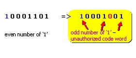
of parity constitutes a simple example of detecting code. This code has a
Hamming distance of 2, therefore any simple error produces an unauthorized word. To correct d errors, it is necessary that the code
has a Hamming distance of 2*d+1.
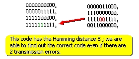
In
this case, the distance between each codeword is such that even if d simple errors occur, the original
codeword remains closer to the transmitted codeword: than to another one.
Let
us suppose that we want to build a code with m bits of data and r
control bits that permits to correct the simple errors. For each one of 2m possible codewords, there
is n unauthorized codewords located
at a 1 bit distance from the authorized code. They are obtained starting from
the authorized codeword by reversing one of its n bits. With each of 2m
possible combinations of data bits, one associates n+1 words of n bits.
As
the total number of words of n bits
is 2n, the following
relation must be checked:
(n+1) * 2m < 2n
By
using the equality n=m+r, the
inequality becomes:
(m+r+1) <2r
Knowing
m, this inequality allows us to
determine the minimal number of control bits necessary to correct the simple
errors.
Question:
How
much bits of control (r) is it
necessary to add to a data word of 10 bits to be able to correct a simple
error?
# simple error correction
d = int(raw_input("number of data bits:
"))
r=1
while 1:
rv=
pow(2,r)
lv =
d+r+1
if(rv
> lv):
break
r = r +1
print("the minimal number of control bits is:
"), r
6.5. Error detection codes
The error correction codes are used for the data
transmissions whenever it is impossible to ask for a retransmission, this is a
case of real-time applications. For alla applications less sensitive to
transmission delays we use error detection with retransmission.
# error correction versus error detection
# Attention: one error in the sent data
bs = int(raw_input("block size in bits:
"))
ds = 1000 *int(raw_input("data size in
Kb: "))
r=1
while 1:
rv=
pow(2,r)
lv
= bs+r+1
if(rv > lv):
break
r =
r +1
print("the minimal number of control bits
is: "), r
dsc = ds/bs * r + ds # correction bits + data size
dsd = ds/bs *1 + ds + bs +1 # parity bits + data size + retransmitted
block size
print("total data size for correction in
Kb: "),dsc/1000.0
print("total data size for
detection/retransmission in Kb: "),dsd/1000.0
Example: Let us take as example a channel with simple errors and an error rate
of 10-6. Let us consider storage blocks of 1000 bits. If one wishes to correct
the simple errors, it is necessary to add 10 bits of control per block (1010 bit/block).
For a megabit of data, there will be 10.000 bits of control.
To detect a bad block simply, it is enough to have a
bit of parity (1001 bit/block). With the method of detection and retransmission
the number of additional bits is only 2001
(1000 * 1 + 1001), whereas one needs of them 10.000 with a code of correction.
Although the bits of parity can be exploited for the
detection of the multiple errors, in practice we use the polynomial codes, also
called CRC codes (Cyclic Redundancy Code).
In CRC codes, the bit strings are considered as the coefficients of a
polynomial.
These coefficients take only two values: 0 or 1. A
block of m bits is seen like a
series of coefficients with m active
terms : x m-1 with x0. Such a polynomial is
known as polynomial of degree m-1.
For example, a chain 10101 that includes 5 bits is
represented by a polynomial of 5 terms whose coefficients are 1,0,1,0 and 1: x4+x2+x0.
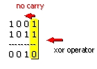
Since the polynomial arithmetic one is made modulo 2, the operations of
addition/subtraction give the same result. Also let us note that arithmetic
modulo 2 does not generate the carries.
To use a polynomial code, the transmitter and the
receiver must agree on the choice of a generating polynomial G (X). The generator must have its most
significant bit - MSB and least significant bit -LSB bits equal to 1.
The data block of m
bits, must be longer than the generating polynomial.
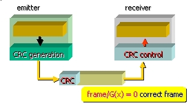
The basic idea consists in adding, at the end of the
block, the control bits so that the frame (bloc
+ control bits) is divisible by G
(X).
When the receiver receives the frame, it divides it by
G (X). If the remainder is non null,
an error of transmission took place.
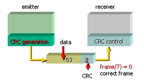
Example
(decimal):
data
- 53
generator
- 7
530:7 75 - the quotient
49
40
35
5 - complement of 7 is 2; thus the value to be generated is 532
Example
(binary): : 1101011011, generator: 10011;after addition of 4 bits with 0s:11010110110000
11010110110000
10011
10011
10011
00001
00000
00010
00000
00101
00000
01011
00000
10110
10011
01010
00000
10100
10011
01110
00000
1110 - the remainder
The emitted frame is: 11010110111110
The three generating polynomials which were
standardized are:
•
CRC-16 = x16+x15+x2+1
•
CRC-CCITT= x16+x12+x5+1
•
CRC (802.3 - Ethernet) = x32+x26+x23+x22+x16+x12+x11+x10+x8+x7+x5+x4+x2+x+1
All these polynomials contain x+1 as first factor. Polynomials CRC-16 and CRC-CCITT are used for
characters coded on 8 bits. They detect all simple and double errors, all
errors comprising an odd number of bits and all packages of errors shorter than
16 bits.
They detect with a probability of 99,997% the packages
of errors of 17 bits and with a probability of 99,998% the packages of errors
longer or equal to 18 bits.
Important:
In
practice, a simple register with shift is enough to obtain the CRC code. That
is why the polynomial coding and decoding is performed directly by the electronic
circuits transmitting the data on physical line.
6.6. Summary
In this chapter we
have studied basic coding techniques used to build frames and
detection/correction codes.
The frames may be
marked by the violation of the physical codes or by specific binary sequences.
In the second case a mechanism called bit transparency has been introduced to
distinguish between the frame markers and the internal data having the same
binary format.
The error correction
codes are used for the transmission with real-time constraints , where the
retransmission time is prohibitive. In this case the tries to retrieve the
original information from the received data frame. The error detection codes
are used when the transmission delays are allowed. In this case the erroneous
frames can be retransmitted. The existing CRC codes allows for a high
probability of simple and multiple errors detection In many cases this probability is equal to one.
In the next chapter
we are going to present simple link protocols based on error detection and
correction techniques.