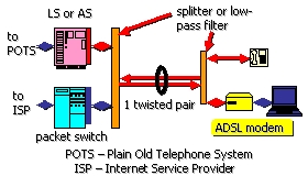
One of the important characteristics of the ADSL is
the fact that it supports the analogical service of voice (Plain Old Telephone Service, or POTS). A special device called splitter separates the low frequency
analogue channel of 4KHz from the high frequency based digital channel.
The
traditional analogue channel is still under the control of a telephone switch
(LS – local switch), and the digital channel is redirected to a packet switch
device such as Ethernet or ATM switch. This device multiplexes several input
links and is called DSLAM for DSL access multiplexer.
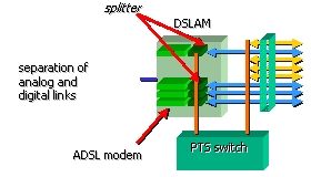
The
DSLAMs are essential entry points in standard ADSL. The ADSL modems in a
DSLAM carry out a simple aggregation of
the traffic. All the bits and packages transiting the DSLAM are deferred to the
services by simple circuits. For example, if there are 10 ADSL customers
communicating with 2 Mb/s in the downward direction and with 64 Kb/s in the
upward direction, then the connection between the access node and the network
services, must be at least of 20 Mbit/s (10x2 Mbit/s) in the two directions in
order to avoid the congestion and the rejection of the packets. Note that the
data rate of this connection must be the same in two directions (20 Mbit/s)
; This is due to the operation in
duplex mode.
ADSL standards
Like any other technology of communication, the ADSL
needs the standards. All technologies evolve through a phase of exploration and
experimentation (at their beginnings the cars and the planes took many sizes
and odd forms). Before consumers accept a new technology, it must sufficiently
standardized to satisfy everyone. People want that technology and the products
are homogeneous, independent of a particular manufacturer, and compatible with
other products in the same category.
Nowadays
ADSL is an established technology with several sub-standards (ADSL, ADSL2,
ADSL2+, etc). In general the newer standards must be compatible with the
previous ones and the corresponding implementations should be able to
cooperate.
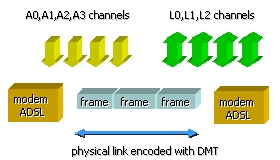
The total frequency band exploited by the
standard is divided into two bands: the
upstream band and the and
downstream band . If the same frequencies are used with downstream and upstream
the echo cancellation must be used. The echo cancellation eliminates the
possibility that a signal reflected in one direction is interpreted like a
“transmitter” in the opposite direction.
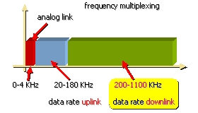
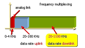
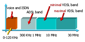
The above figures show the decomposition of frequency band into three
sub-bands. The lowest frequencies represent the analogue link , the higher
frequencies are used to build the uplink and downlink channels. Note that the
downlink channel occupies much bigger bandwidth than the downlink channel.
If both channels are superposed the echo cancellation techniques are
required.
ADSL modulation
technique
The official modulation method for an ADSL line is
Discrete Multi Tone. - DMT. DMT divides
the whole bandwidth into a great number of secondary canals. Technically, the
secondary canals are called subcarriers.
Above the baseband preserved for the analogical channel, the totality of the
bandwidth is extended to 1;1 MHz (ADSL1) and is divided into 256 secondary
canals. Each secondary canal occupies 4.3125 KHz, which gives a total bandwidth
of 1.104 MHz. Certain secondary canals are reserved for specific functions,
others are not used. For example, channel # 64 to 276 KHz is affected to the
piloting signal.
The
majority of DMT systems uses only 249 or 250 secondary canals for information.
Low secondary canals from #1 to # 6 are assigned to analogue voice. Because 6
multiplied by 4.3125 Hz gives value of 25.875 KHz, it is common to see 25 KHZ
like starting point of ADSL services.
When
the cancellation of echo is used there are 32 uplink channels, usually starting
with channel # 7, and 250 downlink channels.
When
one uses only the frequency multiplexing, there are typically 32 uplink
channels and only 218 downward channels because they do not overlap any more.
The downlink channels occupy the low part of the spectrum for two reasons:
•
the attenuation of signal is lesser on the lower frequencies,
•
the losses of the signal at the higher end of the spectrum are very
important and unacceptable for the control signals.
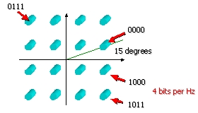
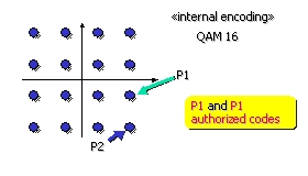
The simple channels use Quadrature
Amplitude Modulation - QAM modulation. QAM simply modulates the amplitudes of
two waves in the quadrature (with 90° shift).
For
example a QAM may apply four different amplitudes for each of the two waves.
These
four amplitudes may be labeled as A1 to A4. In this case 16 different instances
of signal are obtained. This is done providing all possible combinations of two
amplitudes of the sinusoidal and co-sinusoidal waves.
The set of 16 instances/states creates QAM 16 code
characteristics called «constellation». The following figure represents the constellation of 16
states generated using four amplitudes A1 to A4.
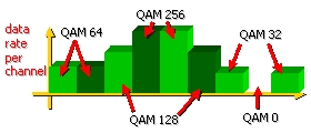
If the number
of possible amplitudes is extended to 8 , QAM constellation provides 256
states, that also means that one Hertz
of bandwidth may carry 8 bits (spectral efficiency). of data. Having a 4 KHz
bandwidth a single channel may carry 32 Kb/s.
When the
peripherals ADSL which employ DMT are activated, each secondary canal “is
tested” for the attenuation. In practice, the test is a procedure of data
exchange where the parameter used is the gain (opposite of the attenuation). The
total capacity of transfer is the sum of all the binary rates sent on all
active secondary canals. All the secondary canals are constantly controlled for
the performance and the errors. A finer granularity of channels may provide
more optimal conditions to increase the global performance. On the other side
more channels means more complexity of the signal modulation and demodulation.
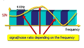
Note that depending on the attenuation conditions on some frequencies an
individual channel can “be put at zero.”
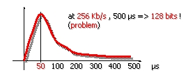
Transmission errors
The signals sent over copper pairs are objects of many kinds of
perturbations. These include the unpredictable impulsive noise that can induce
transmission errors over the long periods of 500µs. The most probable length of
perturbations is about 50µs. In this case several tens of bits may be damaged.
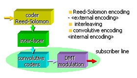
The ADSL modems use three
combined techniques to « repair » the errors. The are:
·
Reed-Solomon encoding that performs an
external encoding before the transmission of bit frames on the line.
·
interleaving that spreads the errors over a
much longer bit string, this avoids to have very long bursts of errors
·
convolutive encoding that provides a
very robust internal encoding of individual bits sent to the modulator
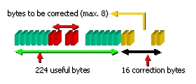
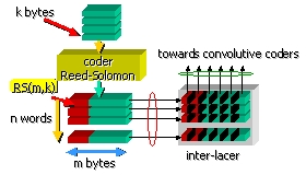
The
Reed-Solomon encoding is based on RS(240,224) code – 16 correction bytes
allowing for the correction of maximum 8 bytes (64 bits).
The interleaving mechanism
accumulates a number of codewords and sends the recombined parts of the
codewords in a different order. This operations cuts in smaller pieces the potential bursts of errors. The main
drawback of interleaving is the introduction of important transmission delays
approaching several or tens of
milliseconds. Such delays may be not acceptable for real time transmissions.
The aim of the convolutive encoder is to find out the most probable word
code using a historical trace of the recently transmitted code symbols.
For
example, to select from two authorized code possibilities: P1 and P2, the most
probable code associated to the received code P.
The last operation
before the sending the data on the line for the modulation is the convolutive
encoding that inserts some ‘historical’ relation to the selected modulation
states.
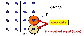
For example, during the decoding phase at the receiver
end , the receiver takes into account the historical trace of the received
code and deduces that the P1 code is more
probable.
At the receiving end we have the following architecture:
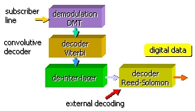
When comparing to the emitter architecture, the functional blocks
operate in the inverse order. It is the receiver starts with the demodulation
then the binary string transits through the convolutive decoder that finds out
the most plausible binary codes. These codes are de-interlaced and pushed
through the Reed-Solomon external decoder.
9.3. ADSL frames
The transfer of the
data between the access node and the
subscriber interface is carried out by ADSL frames. The binary flow inside the
frames can be broken up to the maximum of
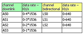
7 transport channels (bearer channels).
The channels of downward simplex
transport are of two types:
•
downlink channels numbered by AS0. AS3 (maximum 4),
•
uplink channels LS0. LS2 (maximum 3).
Each bearer channel
of can be programmed to transfer a multiple number of 32 Kb/s secondary channels
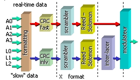
The
data flow may separated into two sub-streams one carrying real-time data, the
second carrying ordinary data. The real time data do not transit through the
interleaving block and can be send more rapidly than the ordinary data pushed
through inter-leaver. We should underline that the real-time data are less
protected against the burst errors than the ordinary data.
The following figure
shows the organization of ADSL frames.
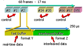
An ADSL super frame
is composed from 68 frames and is sent on the line every 250 µs. Each of the
simple frames is built from two parts: the fast buffer for real time data and
the interleaved buffer for ordinary data. Certain frames have specific
functions. For example frame # 0 and # 1 contain the error control (CRC) and indicator (IB). Other indicators
are carried in frames # 34 and # 35. At the end of the super-frame we find the
synchronization frame.
The
fast buffer contains the synchronization information. The number of bytes
carried by a channel is calculated as a function of the bandwidth of the
allocated DMT channels.
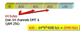
Example
of frame configuration:
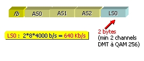
Let
us consider a configuration with support channels AS0, AS1, and AS2, each one
sending 64 bytes in each ADSL frame.
We
have here three down-link transport channels with the data rate of: 64 bytes* 8
bits/byte * 4000/sec = 2,048 Mb/s;(global data rate = 3*2,048 Mb/s). In this configuration, the up-link channel LS0
transmits the data in two directions with the data rate of 2 bytes* 8 bits/byte
* 4000/second = 64 Kb/s
9.4. VDSL
VDSL is a high speed DSL technology based on mixed physical media
including copper and glass fibre cables. VDSL offers very high data rates - up to 100Mb/s in downlink direction..
The
downlink data rate over the distance shorter than :
·
• 200 m is 100 Mb/s,
·
• 1 Km is 30 Mb/s
·
• 1.5 Km is 15 Mb/s.
The
uplink data rate is from 1.5 Mb/s; depending on the requirements it may be
equal to downlink data rate. It may be the case of symmetric lines to connect
the VDSL based servers.
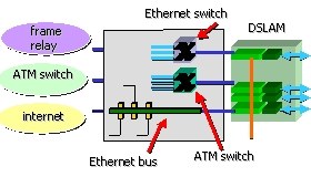
Frames and link protocols
over ADSL
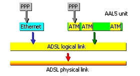
The principal use of
the ADSL links is the transmission of Internet datagrams. These datagrams are
carried in physical frames such as Ethernet frames or ATM cells. The ADSL
channels provid the transfer capacity for these frames. The Ethernet frames
carry up to 1500 data bytes or 1492 data bytes plus the PPP link fields. The
ATM application protocol number 5 (AAL5) allows us to build the data containers
of 9180 bytes excluding PPP fields.
Imagine that you have
a 2048 Kb/s ADSL channel. What is the useful data rate for two Ethernet based
transfer and for the ATM based transfer. Take into account the presence of PPP
fields (8 additional bytes) in each
packet. The solution is given in the first exercise.
9.5. Summary
In this chapter we have studied xDSL technology
(DIGITAL Subscriber Loop) insisting
on its principal alternative ADSL. ADSL links will allows the subscribed to
fully benefit from the resources and the services of the Internet and Wide World Web. The data rates
offered by ADSL links are at least ten times superiors to the data rates
of traditional modems., Once available
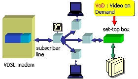
for all the subscribers of the telephone network, ADSL links will provide the
users with a large range of video services including Video on Demand and
educational television.